
Fabricated HDPE Fittings
Large-diameter fittings shaped to suit project geometry, manufactured from PE100 pipe sections and butt-fused under qualified procedures.
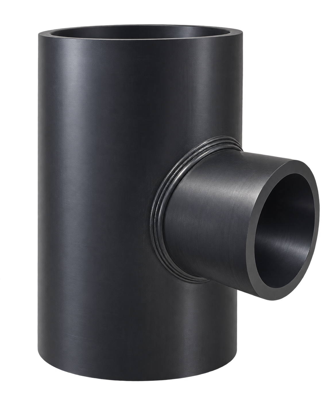 UPI fabricated reducing tee
Made to the project drawing
Union Pipes Industry fabricates HDPE fittings for large-diameter pressure pipelines. Pipe diameter and SDR, fitting geometry and end dimensions are selected for each project, with the final configuration and pressure suitability confirmed against the approved item drawing.
Flexible geometry
Angles, branches and end lengths are defined to suit the project pipe layout.
PE100 pipe sections
Compatible pipe sections are selected according to the project pipe design.
Pressure by design
Pressure class and availability are confirmed for each fitting configuration.
Technical overview
Portfolio range and technical references from the UPI fabricated fittings brochure.
Product range
Flexible angles and branch layouts manufactured to the approved project drawing.
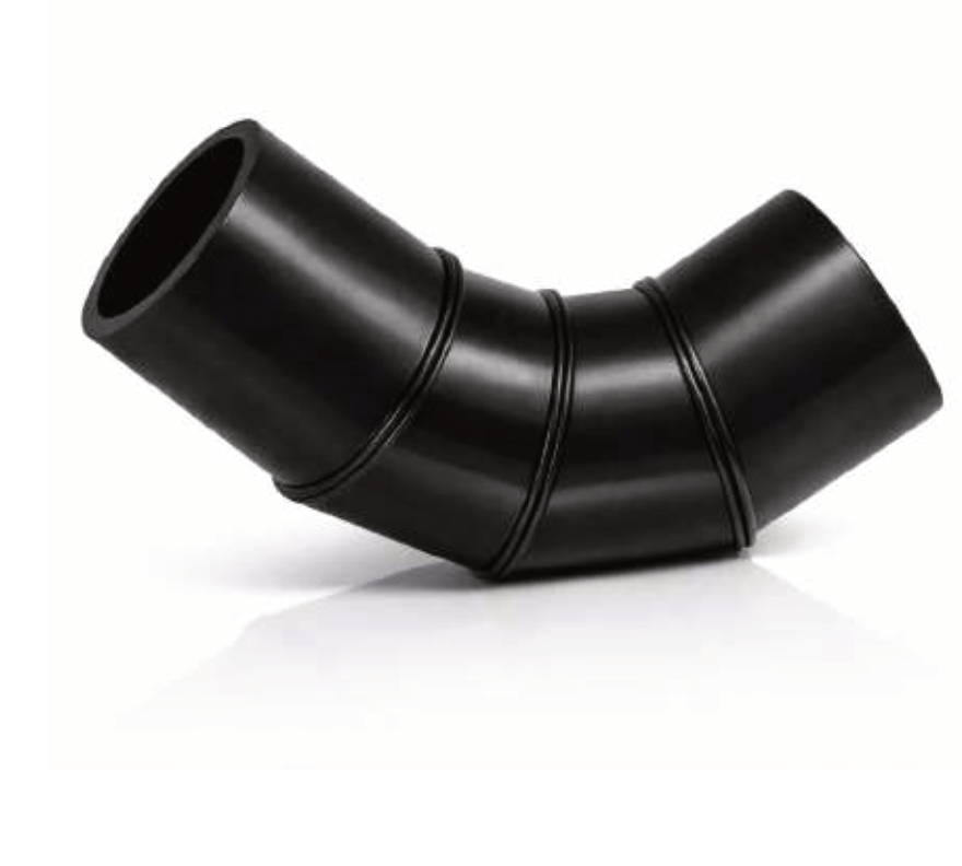 Direction changes
Segmented elbows
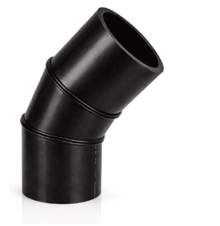
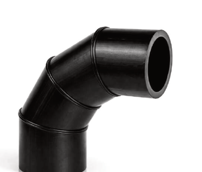
Bend angles above 7°. Confirm angle, centerline radius, end lengths and segment count for each design.
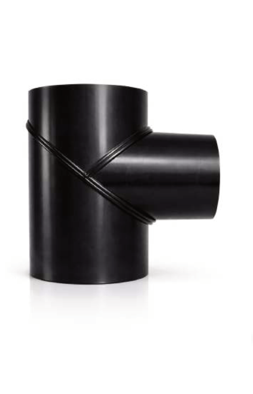 90° equal branch
Equal tees
A PE100 tee with equal main and branch outside diameters. End lengths and branch position follow the approved drawing.
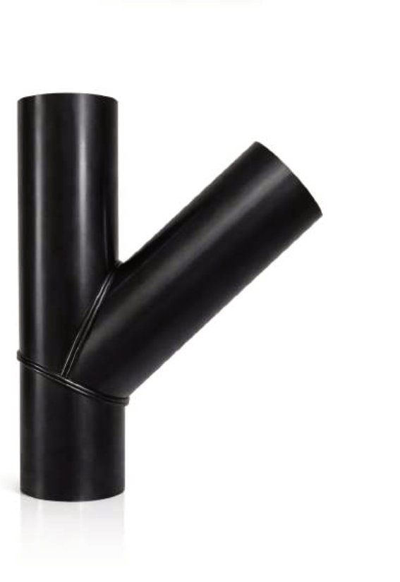 45° / 60° branch
Y tees
Inclined branch fittings for directional pipeline take-offs. Main and branch sizes, SDR and end lengths are selected per design.
90° reduced branch
Reducing tees
Main OD 110–1200 mm; branch OD 50–630 mm; SDR 6–26. Size combinations and pressure suitability are confirmed per item drawing.
 Wall and slab penetrations
Puddle flanges
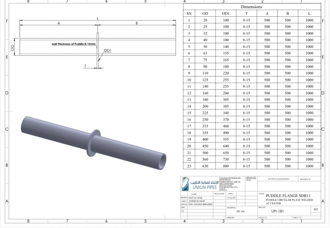
PE100 / SDR 11 drawing basis. Pipe OD and puddle plate OD1 follow the dimension schedule below; installation and sealing details require confirmation.
Segmented elbows
Direction changes produced from butt-fused pipe segments. More than four segments are available; segment count and pressure class are checked for each item design.
Puddle flange dimensions
UPI SDR 11 drawing schedule. All dimensions are in millimetres. A = 500 mm, B = 500 mm, L = 1000 mm and T = 8–15 mm.
| Pipe OD (mm) | Puddle plate OD1 (mm) |
|---|---|
| 20 | 100 |
| 25 | 100 |
| 32 | 100 |
| 40 | 100 |
| 50 | 140 |
| 63 | 155 |
| 75 | 165 |
| 90 | 180 |
| 110 | 220 |
| 125 | 255 |
| 140 | 255 |
| 160 | 280 |
| 180 | 305 |
| 200 | 305 |
| 225 | 340 |
| 250 | 370 |
| 315 | 460 |
| 355 | 490 |
| 400 | 555 |
| 450 | 640 |
| 500 | 650 |
| 560 | 730 |
| 630 | 800 |
Project engineering
Provide these inputs for the project-specific fabricated fitting drawing.
Main pipe OD
Connecting pipe outside diameter.
Branch OD
Branch diameter, where applicable.
SDR / material
Pipe wall ratio and PE grade.
Geometry
Angle, radius or branch position.
End dimensions
Run and branch end lengths.
Pressure class
Required service pressure for review.
Inspection & documentation
Drawing-based checks and project-specific deliverables are agreed for each order.
Drawing control
Check OD, branch position, angles and end dimensions.
Material & welding
Select compatible PE100 pipe and the applicable joining procedure.
Dimensional review
Compare key finished sizes with the approved drawing.
Project records
Agree inspection and test documentation for the order.
Need a project-specific fitting?
Contact our technical team with the pipe dimensions, fitting geometry and pressure requirements to coordinate the approved item drawing.
Technical information and product images are based on the UPI Fabricated Fittings Brochure 2026. Final configuration and pressure suitability follow the approved item drawing.