
HDPE Solid Wall Pipes
Reliable piping solutions for water, utilities, infrastructure and industry.
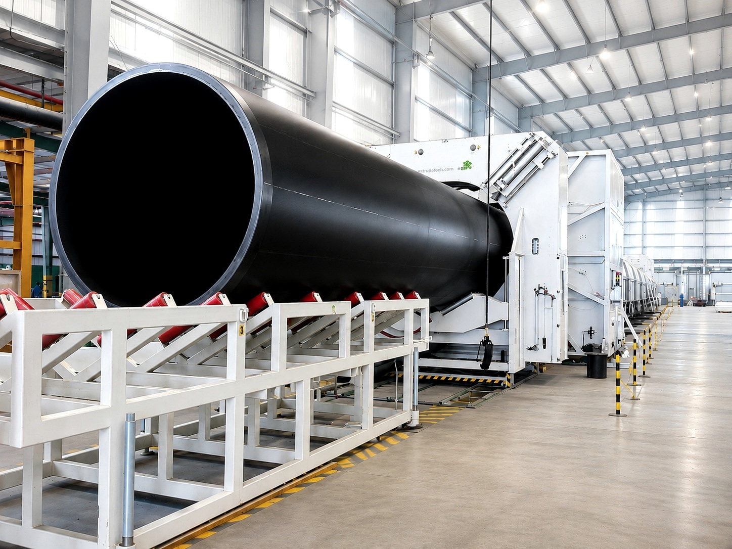
Engineered for performance
UPI manufactures PE100 solid wall pipes in King Abdullah Economic City, Rabigh, Saudi Arabia, for water, gas, fire protection and infrastructure projects.
Leak-tight connections
Fusion joints create a continuous piping system and help reduce leakage.
Corrosion resistance
HDPE does not rust or scale, while its smooth internal bore supports efficient flow.
Flexibility and long service life
Impact resistance, flexibility and lightweight handling support installation and ground movement. Service life depends on correct design, installation and operation.
Product range & applications
The 2026 brochure covers outside diameters from 16 to 2,000 mm, SDR 41 to SDR 6 and PN 4 to PN 32. Supply is in straight lengths or coils, depending on size and project requirements.
Water & irrigation · Blue stripes
PE100 piping for water supply and irrigation, referenced to ISO 4427 and EN 12201.
Fire protection · Red stripes
Fire-water systems referenced to ISO 4427 / EN 12201, with FM approval where applicable to the selected product and approval scope.
Gas distribution · Yellow stripes
Black PE100 pipes with yellow stripes, referenced to ISO 4437 / EN 1555. Preferred SDR options are 17 and 11; the brochure lists gas dimensions from 20 to 630 mm. Smaller sizes can be supplied in coils.
Pressure selection
PE100 water service at 20°C, with design coefficient C = 1.25. SDR is the ratio of outside diameter to wall thickness.
| SDR | 41 | 33 | 26 | 21 | 17 | 13.6 | 11 | 9 | 7.4 | 6 |
|---|---|---|---|---|---|---|---|---|---|---|
| PN / bar | 4 | 5 | 6.3 | 8 | 10 | 12.5 | 16 | 20 | 25 | 32 |
Temperature derating
For continuous operating temperatures above 20°C, the brochure gives the following PE100 pressure reduction factors.
| °C | 20 | 25 | 30 | 35 | 40 | 45 | 50 |
|---|---|---|---|---|---|---|---|
| Factor | 1.00 | 0.93 | 0.87 | 0.80 | 0.74 | 0.675 | 0.61 |
International & American standards
The brochure references ISO 4427, EN 12201, ISO 4437, EN 1555 and DIN 8074/8075, together with ASTM F714, ASTM D3035, ASTM D2513, ASTM D3350 and AWWA C906. Applicable references and conformity documents depend on the selected product and service.
Metric dimensions
Detailed OD and wall thickness tables are provided in the brochure, with dimensional tolerances referenced to ISO 11922-1, Grade V.
American IPS range
The brochure lists PE4710 / PE100 IPS sizes from 4 to 42 inches, with size-dependent DR / pressure-class options under AWWA C906.
IPS pressure options
DR11 / PC200 psi; DR9 / PC250 psi; DR7.3 / PC317 psi; DR7 / PC335 psi. Refer to the brochure table and confirm availability for the required size.
Joining methods
Butt fusion
Referenced to DVS 2207-1 / ISO 21307. Clean preparation, alignment, verified fusion parameters and full cooling are essential.
Electrofusion
Referenced to ISO 12176-2. Prepare and align the joint correctly and follow the approved fitting and equipment procedures.
Flanged connections
Stub ends and backing rings connect to valves, pumps and other materials. Match connections to the pipe size, SDR, material and project requirements.
Manufacturing & quality control
Production includes approved raw materials and batch identification, controlled extrusion and stripe co-extrusion, vacuum sizing, cooling, marking, cutting and final inspection before dispatch.
Material traceability
Material certificates and batch records, density and melt flow rate checks.
Dimensions & appearance
Outside diameter, wall thickness, ovality, surface quality, marking and length checks.
Performance testing
Hydrostatic testing at controlled temperature, tensile strength and elongation, and oxidation induction time (OIT), with final documentation and release checks.
Handling & installation
Lift and store carefully
Use wide fabric slings and balanced lifting. Avoid chains and sharp edges; provide level supports, secure stacks and protect pipe ends.
Prepare the trench
Provide firm, continuous bedding, remove sharp objects and compact the haunch zone in accordance with the project requirements.
Inspect and backfill
Inspect pipes before lowering and backfill evenly. Follow the approved installation procedure, local safety requirements and manufacturer guidance.
Plan your piping system
Explore the product range, technical specifications and applications in the brochure.